Difference between revisions of "MainPage:Nuclear:Summer2012:Cable"
Jump to navigation
Jump to search
m |
|||
| Line 11: | Line 11: | ||
<br> | <br> | ||
[[File:LengthvsDelay.jpg]] | [[File:LengthvsDelay.jpg]] | ||
| − | <br> | + | <br><br> |
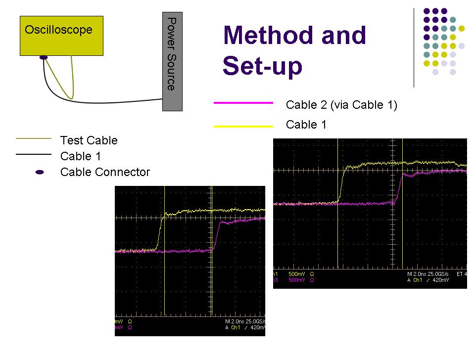
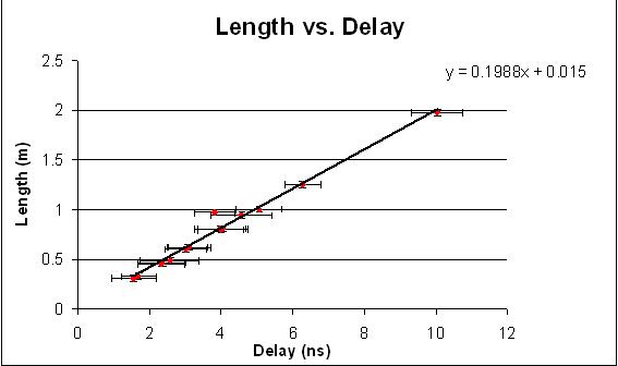
<font size='3'> This chart shows the relation between the length of each of the cables and the delay that they experience, as found using the above-described method. The slope of the graph (as shown by the trendline equation) represents the approximate speed at which the current passing through the cable is traveling. The units for this slope are meters per nanosecond. The error bars vertically represent the uncertainty in the length measurement while the horizontal error bars are the range of the possible delay. </font> | <font size='3'> This chart shows the relation between the length of each of the cables and the delay that they experience, as found using the above-described method. The slope of the graph (as shown by the trendline equation) represents the approximate speed at which the current passing through the cable is traveling. The units for this slope are meters per nanosecond. The error bars vertically represent the uncertainty in the length measurement while the horizontal error bars are the range of the possible delay. </font> | ||
Revision as of 09:56, 27 June 2012
| ⇐ Back to Summer 2012 page |
| ⇐ Back to the Main_Page |
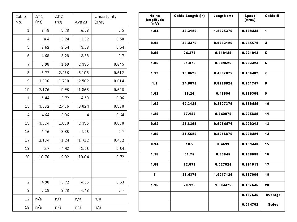
Cable Delay Information | Cable Noise/Length Info.


This chart shows the relation between the length of each of the cables and the delay that they experience, as found using the above-described method. The slope of the graph (as shown by the trendline equation) represents the approximate speed at which the current passing through the cable is traveling. The units for this slope are meters per nanosecond. The error bars vertically represent the uncertainty in the length measurement while the horizontal error bars are the range of the possible delay.