Difference between revisions of "MainPage:Nuclear:KaonDetector:Wires"
| Line 19: | Line 19: | ||
|- | |- | ||
| valign="top"| | | valign="top"| | ||
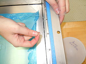
| − | [[File:wires_nylon01.jpg|thumb|center|300px| | + | [[File:wires_nylon01.jpg|thumb|center|300px|Studying what would be a good knot for placing wires strained.]] |
| valign="top"| | | valign="top"| | ||
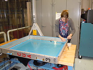
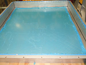
| − | [[File: | + | [[File:Jlab_training_04.jpg|thumb|center|300px|Nylon wires placed to test how we would place wires on the trays.]] |
|} | |} | ||
| Line 32: | Line 32: | ||
|- | |- | ||
| valign="top"| | | valign="top"| | ||
| − | [[File: | + | [[File:wires_steel01.jpg|thumb|center|300px|Wires placed initially in diagonals, making a mesh on the tray.]] |
| valign="top"| | | valign="top"| | ||
| − | [[File: | + | [[File:wires_steel02.jpg|thumb|center|300px|Mesh formed by wires placed in diagonal. It showed that diagonals are not a good strategy.]] |
| + | | valign="top"| | ||
| + | [[File:wires_steel03.jpg|thumb|center|300px|How the wires look like after being strained.]] | ||
| + | |} | ||
| + | |||
| + | Finally, we place the stainless steel wires in horizontal and vertical. To see how it would work on the top of the stacked aerogel tiles, we places few tiles in the tray. Nine tiles were stacked shifting one layer to the other by about one inch, so they would not have a dead measurement area in between tiles. | ||
| + | |||
| + | As the tiles don't have a uniformity in thickness, it was noted that we will need to select tiles by thickness to stack them accordingly to have thickness uniformity over the tray. And it was also noted that the room to adjust wire position (tightening the bolts) is not too much. | ||
| + | |||
| + | {| border="0" style="text-align:center;" width="100%" | ||
| + | |+'''Wires on the top of stacked aerogel tiles''' | ||
| + | |- | ||
| + | | valign="top"| | ||
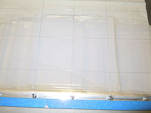
| + | [[File:wires_steel04.jpg|thumb|center|300px|Wires making a mesh on the top of 9 stacked tiles. Now the mesh was done by crossing vertical and horizontal wires.]] | ||
| + | | valign="top"| | ||
| + | [[File:wires_steel05.jpg|thumb|center|300px|Detail of the mesh of 150 micro-meters stainless steel wires.]] | ||
| + | | valign="top"| | ||
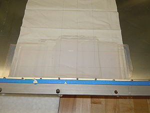
| + | [[File:wires_steel06.jpg|thumb|center|300px|Showing how tiles were stacked by shifting one layer to the other, to avoid dead areas in the detector. Wires were placed on the top of it.]] | ||
|} | |} | ||
Revision as of 21:16, 2 April 2013
| This page is under construction. |
| ⇐ Back to the Kaon Detector page |
First wires assembly - training purpose
In order to be trained to make the final assembly of the aerogel trays, we (Jullianna, Arshak, Marco and Hamlet) did a series of training on how to place the wires that will prevent any eventual fall of aerogel from the tray (March 28-29 2013, at JLab). The idea will be to use the same principle used in the HMS detector, the wires will be placed just for an emergency case. The aerogel should not touch them in general, since these wires are really thin and can easily scratch the tiles.
Our first training was with a thick nylon wire, used for fishing. It was a good exercise to develop knots to make wires strained, as seen bellow.
Then we moved to the thin stainless steel wires (~150 micro-meters in diameter), spare wires from the HMS Aerogel detector. The first idea was to place wires making diagonals, as shown in figure bellow. But this idea didn't work since our detector is a rectangle, the vertical dimension is greater than the horizontal dimension (more bolts in one dimension than in the other).
The lesson taken from this test is that this wires are a more difficult to make be strained. The usage of small springs would be ideal, but if used in such a way to avoid scratching of tiles. The following pictures shows the results of this test.
|
File:Wires steel02.jpg Mesh formed by wires placed in diagonal. It showed that diagonals are not a good strategy. |
Finally, we place the stainless steel wires in horizontal and vertical. To see how it would work on the top of the stacked aerogel tiles, we places few tiles in the tray. Nine tiles were stacked shifting one layer to the other by about one inch, so they would not have a dead measurement area in between tiles.
As the tiles don't have a uniformity in thickness, it was noted that we will need to select tiles by thickness to stack them accordingly to have thickness uniformity over the tray. And it was also noted that the room to adjust wire position (tightening the bolts) is not too much.
|
File:Wires steel06.jpg Showing how tiles were stacked by shifting one layer to the other, to avoid dead areas in the detector. Wires were placed on the top of it. |
