Difference between revisions of "MainPage:Nuclear:KaonDetector:Wires"
(Created page with "{|border="1" cellpadding="2" cellspacing="0" | '''<font style="color:red" size="3">This page is under construction.</font>''' |} <p> {|border="1" cellpadding="2" cellspacing="0...") |
|||
| (11 intermediate revisions by 2 users not shown) | |||
| Line 7: | Line 7: | ||
{|border="1" cellpadding="2" cellspacing="0" style="background-color:lightgray" | {|border="1" cellpadding="2" cellspacing="0" style="background-color:lightgray" | ||
| <font size="2">'''[[MainPage:Nuclear:KaonDetector|⇐ Back to the Kaon Detector page]]'''</font> | | <font size="2">'''[[MainPage:Nuclear:KaonDetector|⇐ Back to the Kaon Detector page]]'''</font> | ||
| + | |} | ||
| + | |||
| + | == Testing different options for wire tension with a prototype == | ||
| + | |||
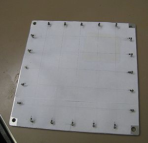
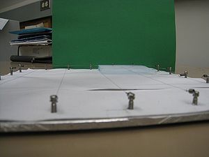
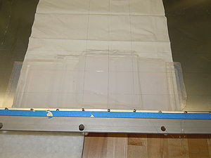
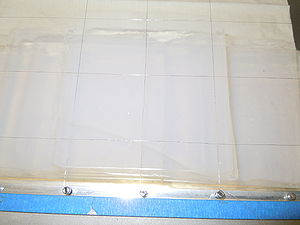
| + | Installing and placing tension on the stainless steel wires is complicated and could damage the aerogel during the installation process. We thus investigated an alternative method for installing the wires using small steel springs. The springs were tied to the wires on 1) one end only, and 2) on both ends. For the latter the spring was cut in halfs. The wires were then installed in an interweaving grid using stainless steel screws to hold the wires in place at the edges of the prototype board. The resulting pattern can be seen in the first figure. The second figure shows how the aerogel tile is held by the wires | ||
| + | |||
| + | Attaching the wires with one spring provides less tension on the wire and could also result in damage to aerogel tiles located close to it (at the sides of the detector box). Having two springs at each end of the wire thus seems preferable. It could be possible to cut the length of the spring further. | ||
| + | |||
| + | {| border="0" style="text-align:center;" width="100%" | ||
| + | |+'''Wires installed in the prototype''' | ||
| + | |- | ||
| + | | valign="top"| | ||
| + | [[File:IMG 3156 small.jpg|thumb|center|300px|Wires installed in the prototype using springs at 1) one end only (horizontal wire in the center), and 2) on both ends (all other wires). The method with two springs is preferable.]] | ||
| + | | valign="top"| | ||
| + | [[File:IMG 3159 small.jpg|thumb|center|300px|Wires installed in the prototype hold the aerogel tile in place.]] | ||
| + | |} | ||
| + | |||
| + | The used wires were: | ||
| + | * Stainless Steel Wire (Type 302/304), Soft Temper, .006" Diameter, 1/4-lb Spool, 2585' Spool | ||
| + | |||
| + | == Getting ready to place wires == | ||
| + | |||
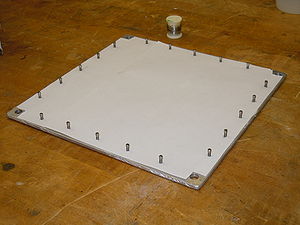
| + | In order to be trained for placing wires on the trays, we prepared at CUA a small version of the tray. It consists only by an aluminum plate and a set of 5x5 bolts, the same used in the actual detector. Bolts were also placed having the same distance from each other as in the actual detector. For testing, it is possible to place one aerogel tile if necessary. | ||
| + | |||
| + | {| border="0" style="text-align:center;" width="100%" | ||
| + | |+'''Testing plate for placing wires on the detector's trays''' | ||
| + | |- | ||
| + | | valign="top"| | ||
| + | [[File:wires_testingPlate.jpg|thumb|center|300px|Testing plate for wires placing. Distance between bolts are the same as in the actual detector (1.3/4 inches).]] | ||
| + | |} | ||
| + | |||
| + | == First wires assembly - training purpose == | ||
| + | |||
| + | In order to be trained to make the final assembly of the aerogel trays, we (Jullianna, Arshak, Marco and Hamlet) did a series of training on how to place the wires that will prevent any eventual fall of aerogel from the tray (March 28-29 2013, at JLab). The idea will be to use the same principle used in the HMS detector, the wires will be placed just for an emergency case. The aerogel should not touch them in general, since these wires are really thin and can easily scratch the tiles. | ||
| + | |||
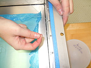
| + | Our first training was with a thick nylon wire, used for fishing. It was a good exercise to develop knots to make wires strained, as seen bellow. | ||
| + | |||
| + | {| border="0" style="text-align:center;" width="100%" | ||
| + | |+'''Thick nylon wires, a first test to develop knots''' | ||
| + | |- | ||
| + | | valign="top"| | ||
| + | [[File:wires_nylon01.jpg|thumb|center|300px|Studying what would be a good knot for placing wires strained.]] | ||
| + | | valign="top"| | ||
| + | [[File:Jlab_training_04.jpg|thumb|center|300px|Nylon wires placed to test how we would place wires on the trays.]] | ||
| + | |} | ||
| + | |||
| + | Then we moved to the thin stainless steel wires (~150 micro-meters in diameter), spare wires from the HMS Aerogel detector. The first idea was to place wires making diagonals, as shown in figure bellow. But this idea didn't work since our detector is a rectangle, the vertical dimension is greater than the horizontal dimension (more bolts in one dimension than in the other). | ||
| + | |||
| + | The lesson taken from this test is that this wires are a more difficult to make be strained. The usage of small springs would be ideal, but if used in such a way to avoid scratching of tiles. The following pictures shows the results of this test. | ||
| + | |||
| + | {| border="0" style="text-align:center;" width="100%" | ||
| + | |+'''Thin stainless steel wires''' | ||
| + | |- | ||
| + | | valign="top"| | ||
| + | [[File:wires_steel01.jpg|thumb|center|300px|Wires placed initially in diagonals, making a mesh on the tray.]] | ||
| + | | valign="top"| | ||
| + | [[File:Jlab_training_05.jpg|thumb|center|300px|Mesh formed by wires placed in diagonal. It showed that diagonals are not a good strategy.]] | ||
| + | | valign="top"| | ||
| + | [[File:wires_steel03.jpg|thumb|center|300px|How the wires look like after being strained.]] | ||
| + | |} | ||
| + | |||
| + | Finally, we place the stainless steel wires in horizontal and vertical. To see how it would work on the top of the stacked aerogel tiles, we places few tiles in the tray. Nine tiles were stacked shifting one layer to the other by about one inch, so they would not have a dead measurement area in between tiles. | ||
| + | |||
| + | As the tiles don't have a uniformity in thickness, it was noted that we will need to select tiles by thickness to stack them accordingly to have thickness uniformity over the tray. And it was also noted that the room to adjust wire position (tightening the bolts) is not too much. | ||
| + | |||
| + | {| border="0" style="text-align:center;" width="100%" | ||
| + | |+'''Wires on the top of stacked aerogel tiles''' | ||
| + | |- | ||
| + | | valign="top"| | ||
| + | [[File:wires_steel04.jpg|thumb|center|300px|Wires making a mesh on the top of 9 stacked tiles. Now the mesh was done by crossing vertical and horizontal wires.]] | ||
| + | | valign="top"| | ||
| + | [[File:wires_steel05.jpg|thumb|center|300px|Detail of the mesh of 150 micro-meters stainless steel wires.]] | ||
| + | | valign="top"| | ||
| + | [[File:Jlab_training_06.jpg|thumb|center|300px|Showing how tiles were stacked by shifting one layer to the other, to avoid dead areas in the detector. Wires were placed on the top of it.]] | ||
|} | |} | ||
Latest revision as of 19:14, 25 April 2013
| This page is under construction. |
| ⇐ Back to the Kaon Detector page |
Testing different options for wire tension with a prototype
Installing and placing tension on the stainless steel wires is complicated and could damage the aerogel during the installation process. We thus investigated an alternative method for installing the wires using small steel springs. The springs were tied to the wires on 1) one end only, and 2) on both ends. For the latter the spring was cut in halfs. The wires were then installed in an interweaving grid using stainless steel screws to hold the wires in place at the edges of the prototype board. The resulting pattern can be seen in the first figure. The second figure shows how the aerogel tile is held by the wires
Attaching the wires with one spring provides less tension on the wire and could also result in damage to aerogel tiles located close to it (at the sides of the detector box). Having two springs at each end of the wire thus seems preferable. It could be possible to cut the length of the spring further.
The used wires were:
- Stainless Steel Wire (Type 302/304), Soft Temper, .006" Diameter, 1/4-lb Spool, 2585' Spool
Getting ready to place wires
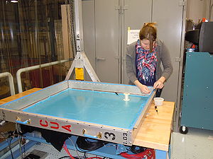
In order to be trained for placing wires on the trays, we prepared at CUA a small version of the tray. It consists only by an aluminum plate and a set of 5x5 bolts, the same used in the actual detector. Bolts were also placed having the same distance from each other as in the actual detector. For testing, it is possible to place one aerogel tile if necessary.
First wires assembly - training purpose
In order to be trained to make the final assembly of the aerogel trays, we (Jullianna, Arshak, Marco and Hamlet) did a series of training on how to place the wires that will prevent any eventual fall of aerogel from the tray (March 28-29 2013, at JLab). The idea will be to use the same principle used in the HMS detector, the wires will be placed just for an emergency case. The aerogel should not touch them in general, since these wires are really thin and can easily scratch the tiles.
Our first training was with a thick nylon wire, used for fishing. It was a good exercise to develop knots to make wires strained, as seen bellow.
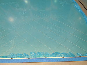
Then we moved to the thin stainless steel wires (~150 micro-meters in diameter), spare wires from the HMS Aerogel detector. The first idea was to place wires making diagonals, as shown in figure bellow. But this idea didn't work since our detector is a rectangle, the vertical dimension is greater than the horizontal dimension (more bolts in one dimension than in the other).
The lesson taken from this test is that this wires are a more difficult to make be strained. The usage of small springs would be ideal, but if used in such a way to avoid scratching of tiles. The following pictures shows the results of this test.
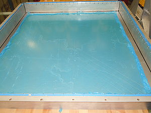
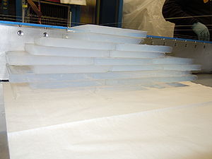
Finally, we place the stainless steel wires in horizontal and vertical. To see how it would work on the top of the stacked aerogel tiles, we places few tiles in the tray. Nine tiles were stacked shifting one layer to the other by about one inch, so they would not have a dead measurement area in between tiles.
As the tiles don't have a uniformity in thickness, it was noted that we will need to select tiles by thickness to stack them accordingly to have thickness uniformity over the tray. And it was also noted that the room to adjust wire position (tightening the bolts) is not too much.
