Difference between revisions of "MainPage:Nuclear:NPS:PWO:LightTransmittance"
| Line 10: | Line 10: | ||
Two types of measurements are planned to be performed with this spectrometers to quantify the crystals transmittance: longitudinal measurement and transverse scan along crystal length. For each of these, a set of benchmark tests were done as described in the following subsections. | Two types of measurements are planned to be performed with this spectrometers to quantify the crystals transmittance: longitudinal measurement and transverse scan along crystal length. For each of these, a set of benchmark tests were done as described in the following subsections. | ||
| + | |||
| + | === Longitudinal Transmittance === | ||
| + | |||
| + | <u>Reproducibility</u> | ||
| + | |||
| + | This first test allowed us to check for reproducibility of the measurements in the spectrometer. This was done by placing a crystal at the center of the spectrometer twice, trying to reproduce the same conditions. | ||
| + | |||
| + | Measurements/tests: | ||
| + | * 1 - Measure transmittance with the PbF2 cube at the center of the compartment. | ||
| + | |||
| + | Pictures: | ||
| + | {| border="0" style="text-align:center;" width="100%" | ||
| + | |+ | ||
| + | |- | ||
| + | | valign="top"| [[File:benchm_longitudinal_PbF2_spectrometer.jpg|thumb|center|340px|BTCM crystal positioned at the center of spectrometer.]] | ||
| + | | valign="top"| [[File:benchm_longitudinal_PbF2_center.jpg|thumb|center|340px|Spectrometer with lid.]] | ||
| + | |} | ||
| + | |||
| + | Results: | ||
| + | {| border="0" style="text-align:center;" width="100%" | ||
| + | |+ | ||
| + | |- | ||
| + | | valign="top"| [[File:benchm_longitudinal_plot_PbF2_reprod.jpg|thumb|center|340px|Measurements of transmittance of PbF2 crystal at different times, to check for reproducibility of measurements.]] | ||
| + | | valign="top"| [[File:benchm_longitudinal_plot_PbF2_Diff_reprod.jpg|thumb|center|340px|Difference between these two measurements.]] | ||
| + | |} | ||
| + | |||
=== Transverse Transmittance === | === Transverse Transmittance === | ||
Revision as of 12:45, 9 November 2015
| ⇐ Back to Neutral Particle Spectrometer |
| ⇐ Back to the Main_Page |
Spectrometer benchmark
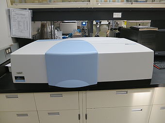
A set of tests were performed in order to understand the repetitivity, reprodutibility, and the effects of some components of the spectrometer in the transmittance measurements of PWO crystals with the Lambda 750 UV/VIS/NIR spectrometer at CUA.
Two types of measurements are planned to be performed with this spectrometers to quantify the crystals transmittance: longitudinal measurement and transverse scan along crystal length. For each of these, a set of benchmark tests were done as described in the following subsections.
Longitudinal Transmittance
Reproducibility
This first test allowed us to check for reproducibility of the measurements in the spectrometer. This was done by placing a crystal at the center of the spectrometer twice, trying to reproduce the same conditions.
Measurements/tests:
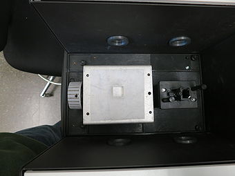
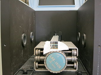
- 1 - Measure transmittance with the PbF2 cube at the center of the compartment.
Pictures:
Results:
File:Benchm longitudinal plot PbF2 reprod.jpg Measurements of transmittance of PbF2 crystal at different times, to check for reproducibility of measurements. |
File:Benchm longitudinal plot PbF2 Diff reprod.jpg Difference between these two measurements. |
Transverse Transmittance
Cloth to cover the spectrometer
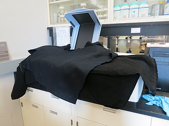
This test allowed us to make sure there is no effect on the transmittance measurements when working with a cloth covering the sample compartment instead the spectrometer's lid. Using the cloth will be necessary since the 20 cm crystals can only be fully scanned in the spectrometer if the lid is removed, since the sample compartment is not big enough.
Measurements/tests:
- 1 - Measure transmittance of a 20-cm BTCP crystal installed at the center of the compartment with the compartment cover installed and closed.
- 2 - Measure transmittance of 20-cm BTCP crystal installed at the center of the compartment without the compartment cover and a black cloth covering the setup. Do not move the crystal between point (1) and this measurement. This test is done without the diagonal slider. Compare the result with that of the previous point. If there is significant noise in the data, check the positioning of the black cloth.
Pictures:
File:Benchm transverse lid.jpg Spectrometer with lid. |
Results:
File:Benchm transverse plot lid cloth.jpg Measurements of transverse transmittance of BTCM crystal with lid and cloth covering the spectrometer's sample compartment. |
File:Benchm transverse diff lid cloth.jpg Difference between these two measurements. |
Slider installation
A slider powered by a stepper motor was configured to position the crystal in the spectrometer compartment for the measurement of transverse transmittance along the crystal. This test allowed us to check for alignment of the crystal to the light beam and for the reproductibility of the measurement using the slider.
Measurements/tests:
- 3 - Install and test the diagonal slider stepper motor with the crystal installed, but no actual transmittance measurement.
- 4 - Measure transmittance of a 20-cm BTCP crystal without the compartment cover, with the black cloth, and with the diagonal slider installed (single crystal position only). If there is significant noise in the data compared to the previous two points, stop to evaluate before proceeding. Check alignment of the crystal to the beam. Check for temporary black cover or paint for the base and any other reflecting surface on the sliding device.
Pictures:
File:Benchm transverse slider1.jpg Slider installed at the spectrometer for transmittance scan along the crystal. |
File:Benchm transverse slider2.jpg Tests of reproductibility with slider in place. |
Results:
File:Benchm transverse plot slider noslider.jpg Measurements of transverse transmittance of BTCM crystal with and without slider in place. |
File:Benchm transverse diff slider noslider.jpg Difference between these two measurements. |
Actual trasverse transmittance measurement
This test allowed us to evaluate, for the first time, the full setup for transverse transmittance scan at a BTCM crystal.
Measurements:
- 5 - Measure transmittance of a 20-cm BTCP crystal at 5-6 points along the crystal with the diagonal slider (compartment cover off, black cloth installed). Determine the variation of the mean at 50% transmittance.
Pictures:
File:Benchm transverse severalPts1.jpg Slider positioning crystal at edge 1. |
File:Benchm transverse severalPts2.jpg Slider positioning crystal at edge 2. |
Results:
File:Benchm transverse plot severalPts.jpg Transmittance of BTCP crystal at several points along its length, positioned with the slider. |
File:Benchm transverse plot variation.jpg Variation of transmittance... |


