MainPage:Nuclear:DVCS-3
| ⇐ Back to the Main_Page |
DVCS-3 Calibration and Analysis
|
DVCS-3 Updates
- Deadtime analysis in progress: main goals include
- Determine the livetime/deadtime correction factor (LTCF)
- Take a trigger rate/live rate and normalize using the current, adjust to the prescale, and then apply the LTCF.
- To make sure the deadtime is correctly computed, the deadtime, current and prescale factors should be in agreement more than 1%, especially for the range of rates in which the deadtime is linear.
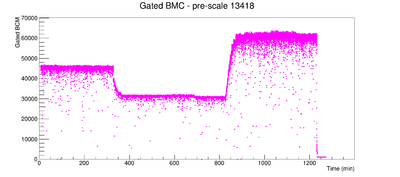
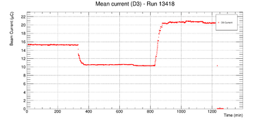
- Currently analyzing run taken in April 2016, 13418 which was a dedicated run for the deadtime analysis, at three different currents (10, 15, 20 uA) using a liquid hydrogen target.
- There are other dedicated deadtime runs taken in February 2016 with a carbon target, 12471 to 12476 at a current of ~5 uA with different prescale factors ( ).
Brief Overview
DVCS-3 was an experiment that ran from 2015-2016 in Hall A (E12-06-114) and is one of the first experiments of the 12 GeV era. The method of DVCS is the cleanest way to access Generalized Parton Distributions (GPDs). More information can be found on the DVCS-3 wiki page.
Experimental Setup
Detector Packages
The electron detector package within the HRS (High Resolution Spectrometer) include scintillators S0 and S2, a Cerenkov gas detector, and Pb-glass calorimeter.
Optics
Deadtime Analysis
The deadtime is defined as the ratio of the number of "live" events going into the electronics or computers to the total number of events. The deadtime calculations are crucial for the calibration process after the experiment. The electronic and computer deadtime need to be quantified to eventually extract precision measurements of the cross section, and thus obtain the neutral pion form factor.
Relevant Terminology
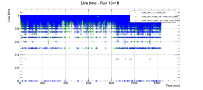
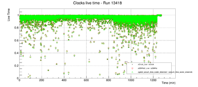
- Scalars - two types of scalars, internal and external to the trigger or detector. For each set of internal and external set of scalars, there are corresponding live and raw scalars. The livetime is then the ratio of the live scalar to raw scalar.
- External Scalars (list borrowed from here). Note that blank spaces after numbers means that those channels were not being used.
- 512ns clock from DVCS trigger crate (1)
- DVCS cosmic trigger
- s0
- s2
- CER
- EDTM
- DVCS external clock or LED trigger
- ARS_stop
- ARS_valid
- DVCS calorimeter ADC_gate
- inverted S0
- inverted S2
- inverted CER
- L1A
- CaloBlock001
- External S2M_CER
- 64ns clock from DVCS trigger crate
- 512ns clock from DVCS trigger crate (2)
- Master_OR
- Master_OR_Live
- HRS_Single
- S2M_CER
- S2M_CER_Scaled
- 103kHz clock from spectrometer
- BCM signal
- Beam Current Monitor (BCM) - works to measure a stable and non-interfering beam current measurement.
- Beam Position Monitor (BPM) - used to determine the position and direction of beam at the target.
- Analog Ring Sampler (ARS) - consists of an array of capacitor cells that work to sample the signals coming from PMTs by storing them. Stop and valid signals are the two signals that control the behavior of the ARS. The valid signal instructs the charge of each capicitor to be digitized, and the stop signal instructs the ARS to stop sampling, which occurs when all the capicitor cells are in a "hold" state, or isolated state.
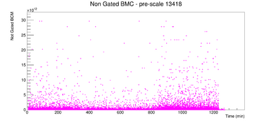
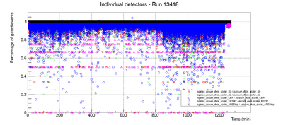
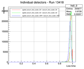
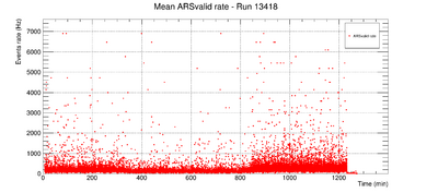
Plots from run 13418: dedicated deadtime analysis run
Important ELog Updates
- Mongi's ELog update: DVCS ELOG LOGIN REQUIRED on May 1, 2017
- Mongi's ELog update: DVCS ELOG LOGIN REQUIRED on May 21, 2017
References
- Munoz, Carlos. Ph.D. Deeply Virtual Compton Scattering in Hall A at Jefferson Lab. 2009.
- Roche, Munoz, et al. Measurements of the Electron-Helicity Dependent Cross Sections of Deeply Virtual Compton Scattering with CEBAF at 12 GeV. arXiv:nucl-ex/0609015.
