MainPage:Nuclear:Summer2012:PrototypeExperiment
| ⇐ Back to Summer 2012 page |
| ⇐ Back to the Main_Page |
The Prototype
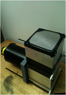
This prototype was designed and built by Marco and Mike (graduated 2012) to model a small section of the SHMS Kaon Aerogel Detector, and to study the characteristics and behavior of both the aerogel panels and the 5" diameter PMTs. It is composed of a single metal light box in which the aerogel panel is held by a wire grid (note that the aerogel is not flush with the sides of the light box). The 5" PMT window is positioned in the bottom half of the light box, and the lid of the light box is removable to allow for changing the number of aerogel tiles stacked within.
The PDF construction plan is available here: File:Body.pdf
The Experimental Setup
The experimental setup will be composed of a triple coincidence with the initial gate being provided by two 2" diameter PMTs with plastic scintillator paddles.
2" PMT Double Coincidence Runs
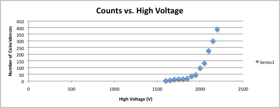
The 2" PMTs are currently being tested in double coincidence for optimization. Runs have been performed over a range of high voltages (1600-2200V). There is approximately 55cm^2 of overlapping scintillator paddle area, meaning that ideally we ought to see approximately 55 muons per minute.
First, coincidence runs were performed with the scintillator paddles of the 2" PMTs approximately 1cm apart. It was found that there was a dramatic increase in the number of coincidences recorded above 2100V. At 2200V the muon count/minute ratio is 20.45 which, although less than half of the ideal expected muon rate, still shows that the setup and equipment is functional and yields strong data.
Ongoing at the moment are double coincidence runs with the same two PMTs set approximately 36cm apart (the height of the prototype with stand), in order to have a baseline for the event rate we can expect from the tripple coincidence testing with the prototype. As is to be expected, the number of coincidences is much reduced from the above number.
Upcoming projects still include making a more permanent rig for the 2" PMTs for prototype testing, as well as possibly making new, longer signal cables.
Initial Prototype Experiments
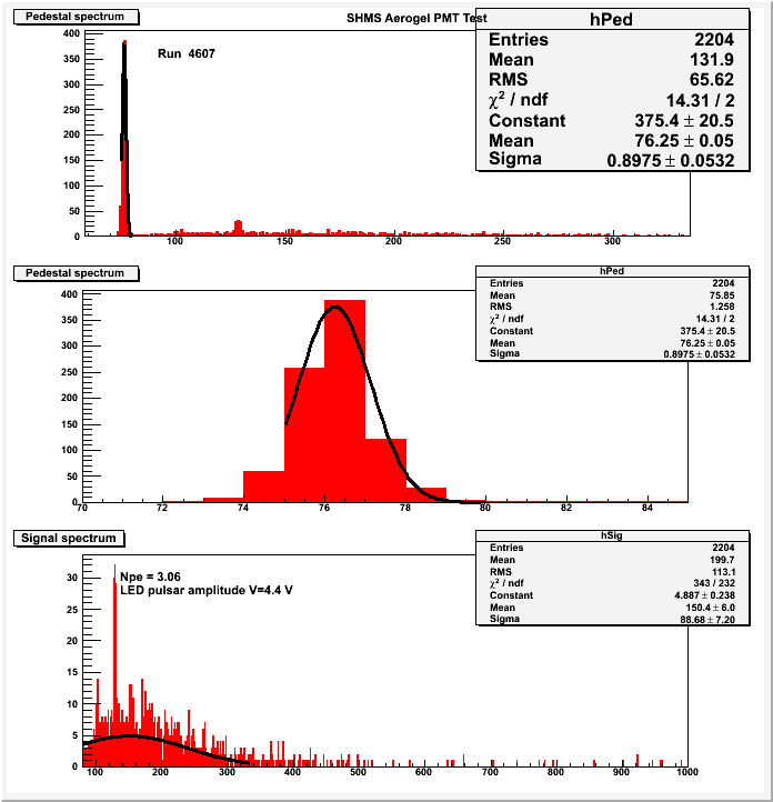
The first prototype experiment was run at JLab using 5cm of aerogel. The gate (80ns) was provided by the double coincidence of the two 2" PMTs (2000V, 50-60mV signal). The 5" PMT signal was between 200mV and 300mV (at 1800V). There were 2204 events in 17 hours.
The calculated number of photo-electrons is 2.6; the simulated number of photo-electrons is 11 on average. This discrepancy is being investigated. The calculated number of photo-electrons from Arthur's prototype with 5cm of aerogel is 9 (however this prototype used Millipore, not Mylar).
A second preliminary test was performed, again at JLab, with 8cm of aerogel. The voltage supplied to the two 2" gate PMTs was also reduced to 1800V. The calculated number of photoelectrons is 5.6.
It is important to note that both the photoelectron calculation for the 5cm and 8cm of aerogel use the same method, but both calculations also use an incorrect attenuation factor. However, despite this error, we can still see the expected trend as the thickness of the aerogel increases.
Testing at CUA
The first round of tests used the Prototype in the "out of box" set up.
First, we tested 5cm of aerogel. Using the "Arthur" method of calculating the number of photoelectrons (using the SEP delta from the "in the box" setup [see below] and assuming that the attenuation factors cancel [see below]) we calculated that the number of photoelectrons is ~3.
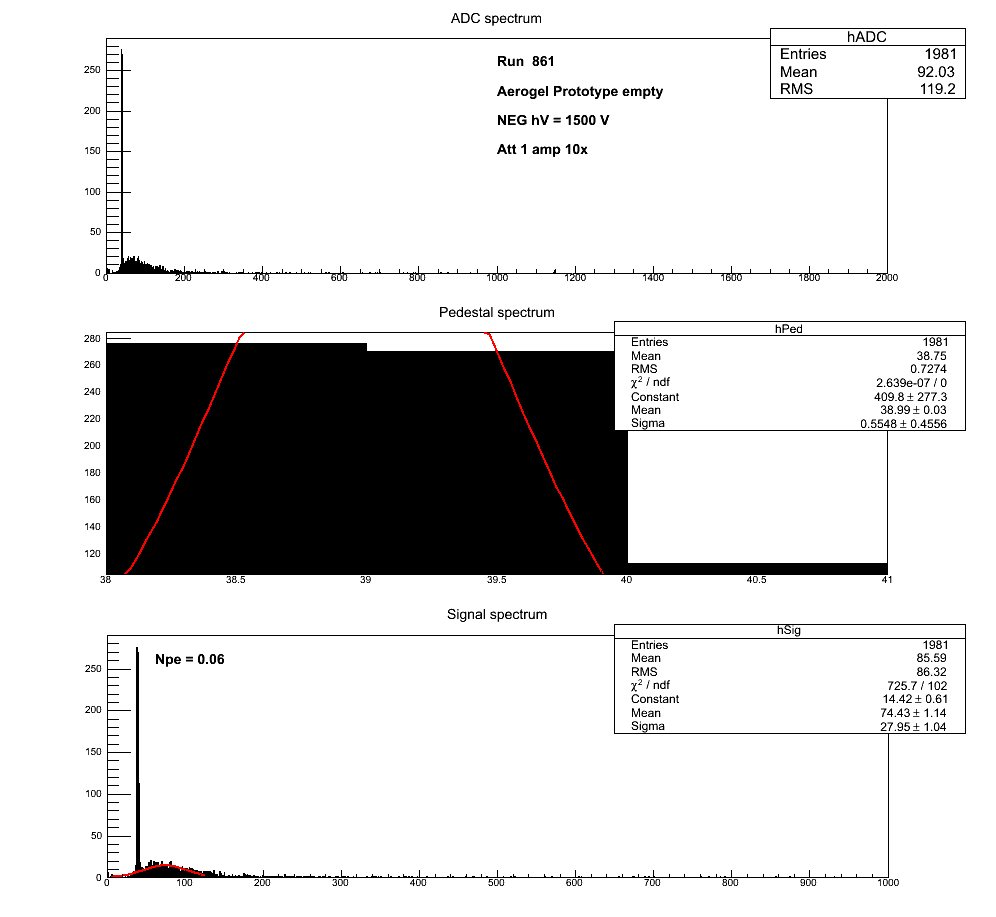
We also tested 8cm of Aerogel and, using the same method, calculated that the number of photoelectrons is ~5.
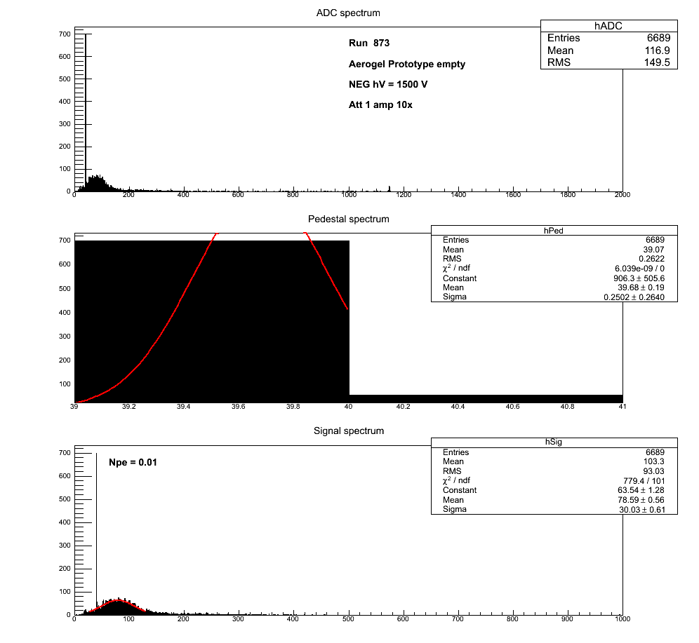
We then made a new setup inside the dark box in order to recalculate the SEP delta and attenuation factor for this experiment (the old SEP for this PMT was from the plastic dark box). The "new" SEP Delta is 13.09, and the attenuation factor is 0.98 (note that the attenuation factor is 0.98 for the out of box and inside the box setups).
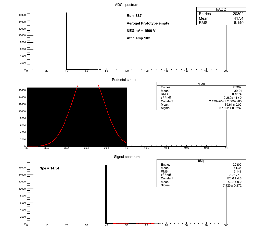
All calculations and data are available on the "Prototype Testing" spreadsheet under "Documentation." (Histograms will come soon)
Attenuation Factor
For both the testing at JLab and at CUA we needed to measure the attenuation factor of the setup so that we can calculate the number of photoelectrons. At JLab we sent a pulse of simliar size and width from a pulse generator through all of the cabling and modules through which the aerogel signal would travel (including a level translator/splitter that reversed the polarity of the signal). The size of the signal was then compared to the size of a signal sent directly to the oscilloscope from the pulse generator. The ratio of signal size was taken to be the attenuation factor of the set up. The same method was used to measure the attenuation factor of the setup at CUA.
Documentation
Excel Workbook File:Coincidence runs.pdf Prototype Testing File:Prototype Testing.xlsx
