MainPage:Nuclear:Summer2015:LEDboard
Introduction
My projects this year were to create a new user interface for the high voltage source and to redesign the LED monitoring system.redesign a Led circuit that would contain many LEDs, activate them by address, then holds the flashing addressed Led in memory and activates another Led to blink, allowing the circuit to have multiple flashing LEDs, in the final circuit there will be around a thousand LEDs. This massive circuit board will be for a calorimeter, that will be use to run experiments on about a thousand crystal samples of lead tungsten at the Jefferson Lab. This circuit would be used to check if the PMT are functioning properly during the whole experiment. My main project was to code a new user interface for our high voltage source. This new interface will be able to turn each channel on/off and adjust their current and voltage. The old interface was not user friendly and was hard to learn and use. This new interface will be designed to be user friendly and intuitive.
LED Ideas
Previous design - At the completion of our project last year we had produced a circuit that addresses LEDs, remembers that LED being addressed, then you can readdressed that LED, so that we can access each LED individually and control the frequency of they’re blinks. This is all done through our controller an Arduino Uno, Which we programmed to perform the required functions. Our prototype did not scale up very well. This is because their were too many components that took up too much space on the circuit board. To fix this we need to look at a circuit with less components and more software manipulation.
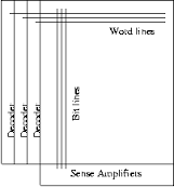
Bit-Line/Word-line - My professor suggested looking into Bit-line/Word-line architecture. Using an ardinuo or other like device, we can send signals down each line. This will activate the transistors on each line. The spot where the lines intersect is where the LED will be. This will only be active when both type of lines transistors are on.My professor suggested looking into Bit-line/Word-line architecture. Using an Arduino or other like device, we can send signals down each line.This will activate the transistors on each line.The spot where the lines intersect is where the LED will activate .This will only be active when both type of lines transistors are active
LED prototype
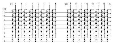
This is example of a LED bit-line/word-line bit shiftier [left]. Here's how it works: we set (and unset) any number of 8 different pins (connected to the "rows" line). Then we pull one of the 16 columns low, leaving the other column pins high, thus lighting up to eight LEDs in a single column. After a short delay, we then change the eight "row" pins and move along to the next column.[1]
I made a small 2 by 2 prototype of the example [right]. I could not get the circuit to work, but I believe this is because the Protoboard is defective.
Original High voltage Interface and Code
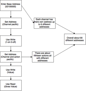
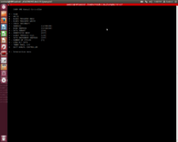
The original code was not very user friendly and just a nightmare to work with. you would have to enter individual addresses to access each channel and their functions.every function for every channel had a different address you needed to know to use the interface.the user could even possibly harm the board by entering the wrong address and entering the wrong values.Overall it was hard to learn and was completely unintuitive.
C++ General Info
C ++ is a programing language used to program on many platforms. It is a imperative object-oriented and generic programing language. It is designed with a bias toward system programming and embedded, resource-constrained and large systems, with performance, efficiency and flexibility of use as its design highlights. This is the language in which our high voltage interface code is written.[2]
New High voltage Interface
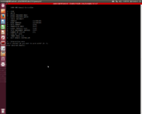
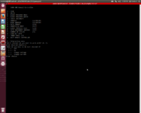
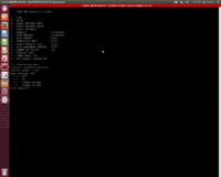
Using case architecture we were able to set up a interactive menu. Second, we changed the write code so you don’t have to enter anything all you need to do is press 0 to turn on the selected channel and 1 to turn off the selected channel. we entered all the addresses of each channel, so the user doesn’t need to enter them. We also change the initial base address to 32100000. You can now change the voltage and current with the press of a button after the channel is selected. we are also able to read the voltage and current values before you enter the new value. the next step is to make a slew of other actions include in the board, like sensing the temperature and each channels status.
Code
Instructions for new interface
1.To open the new interface first press 0.
2.To chose a channel press (0-5) which represent each channel.
3.To chosea action press-0 to turn channel off press-1 to turn channel on press-2 to set voltage press-3 to set current.
4.if you chose input voltage just type the value you want but divide by 10 because the input is multiplied by ten in the code.
Presentation 2015
sources
1. http://nerdclub-uk.blogspot.com/2012/12/bit-shifting-shift-over.html
