Difference between revisions of "MainPage:Nuclear:KaonDetector:AerogelCharacteristics"
| Line 28: | Line 28: | ||
== Refractive index measurement == | == Refractive index measurement == | ||
| − | In order to evaluate the quality of the aerogel tiles we bought for the Kaon Aerogel Detector, an experimental setup was prepared. | + | In order to evaluate the quality of the aerogel tiles we bought for the Kaon Aerogel Detector, an experimental setup was prepared. A few sample of tiles were randomly selected and analyzed. |
| + | |||
| + | Refractive_Index_103_102 | ||
{| border="0" style="text-align:center;" width="100%" | {| border="0" style="text-align:center;" width="100%" | ||
| Line 34: | Line 36: | ||
|- | |- | ||
| valign="top"| | | valign="top"| | ||
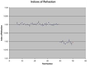
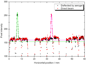
| − | [[File: | + | [[File:Refractive_Index_103_102.jpg|thumb|center|300px|Refractive index of some randomly selected aerogel tiles with nominal index of 1.030 and 1.020.]] |
| + | | valign="top"| | ||
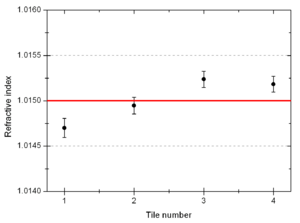
| + | [[File:tile_1to4.png|thumb|center|300px|Refractive index tiles with nominal index of 1.015.]] | ||
|} | |} | ||
Revision as of 18:30, 26 January 2013
| This page is under construction. |
| ⇐ Back to the Kaon Detector page |
Optical properties - Transmittance
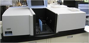
In order to starting measuring the light absorption properties of aerogel, a spectrometer was used for the measurement of the transmittance of some tiles (figure 1).
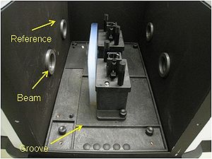
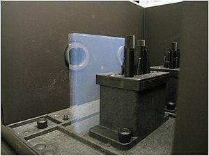
The spectrometer consists of a monochromatic beam of light (1 nm resolution) that is chopped in two different paths: reference and beam (figure 2). One aerogel tile is placed on the beam path (figure 3), so the spectrometer measures the light intensity difference between the beam and reference path, giving the transmittance of the analyzed sample.
Refractive index measurement
In order to evaluate the quality of the aerogel tiles we bought for the Kaon Aerogel Detector, an experimental setup was prepared. A few sample of tiles were randomly selected and analyzed.
Refractive_Index_103_102
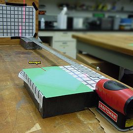
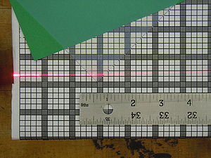
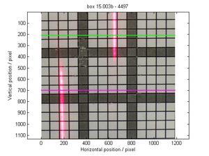
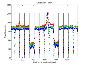
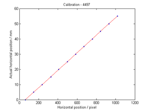
This method consists of a laser sheet, part of it passing through the analyzed aerogel tile and the other part passing out of it. The beam that goes inside the tile get refracted. A reference paper is placed after the tile to mark both the direct and refracted beams. The deviation of the laser is them possible to be measured (using image analysis) for the calculation of the refractive index that causes such deflection.
Kaon Aerogel Detector prototype - Aerogel light yield comparison
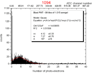
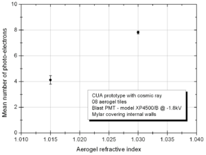
In order to compare the different aerogel (refractive index) we will use in the Kaon Aerogel Detector, a set of cosmic rays data was acquired with the CUA's prototype. Details of the prototype can be found in the Prototype page.
To evaluate the relative light yield of the aerogel tiles with refractive indexes 1.030 and 1.015, the setup was run with the same configuration twice (just exchanging the aerogel).
The setup configuration was kept as follows:
- Cosmic ray configuration (two triggering PMTs with scintillator on the top and bottom of the prototype)
- 08 aerogel tiles
- Mylar covering the internal walls of the prototype
- High voltage of -1.80 kV on the PMT
- Blast PMT for all runs (model XP4500/B s/n 09650, with calibration from run 481)
To see a similar test done for the analysis of the different PMTs options for the Kaon Aerogel Detector, click here.
