MainPage:Nuclear:KaonDetector:PMTCharacteristics
| This page is under construction. |
| ⇐ Back to the Kaon Detector page |
PMT photocathode uniformity
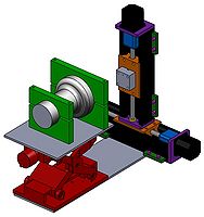
We had developed a scanning setup for analysing the uniformity of the PMT response depending on the incident position of the photons. For that, two steper motors were monted to form a X-Y positioning system, so we can move a LED in front of a PMT window just programming this hardware.
Scanning Setup
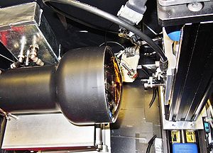
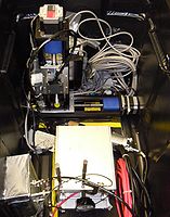
The design and the picture of the scanning setup and can be seen in the following figures.
|
|
The idea of this scanning setup is to flash the blue LED in front of the PMT in different positions. For that, it is necessary to write a code for programming the step motors and upload it into its controller. The written codes for the step motors can found at: COSMOS_Files. It is necessary to run a software to upload it to the controller. This software runs in Windows, so it is not possible to do that with the computer at the lab.
The full range of the scanning is approximately 4.5" x 4.5" (the 5" PMT cannot be completely scanned). The gray piece attached to the step motor is where the LED is placed. There is a small hole (diameter 0.029") in this piece that collimate the light, so that we can define better the position of the incident light. It is also possible to insert paper inside this collimator so that we can reduce the amount of light that goes to the scanned PMT.
An optical fiber was placed in front of the LED and was connected to a reference PMT. It is a 2" PMT placed in the bottom of the box. We can use the signal from this PMT to see it the LED intensity is not changing during the scanning.
Scanned PMTs
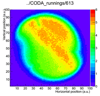
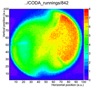
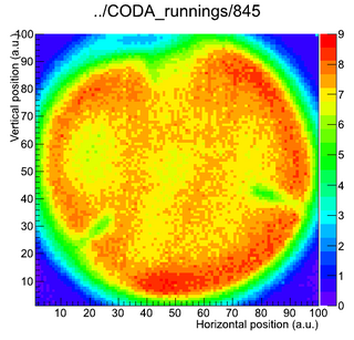
Two types of 5in PMTs were scanning up to July/2012. They are from Blast detector, used for about 10 years at JLab and spares PMTs of the HMS Aerogel Detector.
Control and data acquisition
- Coda Logbook: Some details on the data acquisition are registered in the online logbook.
- COSMOS_Files:Page with the codes used in COSMOS to scan the PMTs
Kaon Aerogel Detector prototype - PMTs comparison
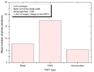
In order to compare the different PMT options we may have to install in the Kaon Aerogel Detector, a set of cosmic rays data was acquired with the CUA's prototype. Details of the prototype can be found in the Prototype page.
All the other configuration of the prototype were kept the same, just the PMT was exchanged between one test and the other. The setup was configured as follows:
- Cosmic ray configuration (two triggering PMTs with scintillator on the top and bottom of the prototype)
- 08 aerogel tiles with 1.030 refractive index
- Mylar covering the internal walls of the prototype
- High voltage of -1.80 kV on the PMT
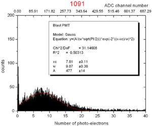 Blast PMT model XP4500/B s/n 09650. Calibration from run 481. 08 tiles of aerogel 1.030. |
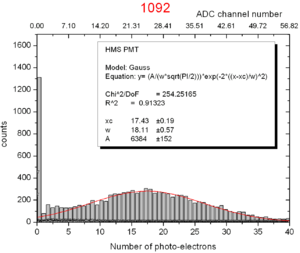 HMS PMT s/n 60158. Calibration from run 805. 08 tiles of aerogel 1.030. |
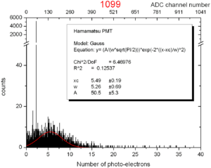 Hamamatsu PMT model R1250 s/n RA1815. Calibration from run 1096. 08 tiles of aerogel 1.030. |
To see the evaluation of the relative aerogel light yield, done in a similar way as we did the PMT analyzis, click here.
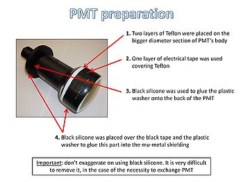
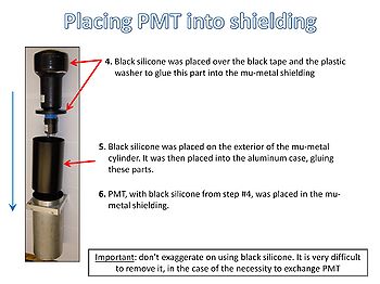
Assembly of PMTs in shielding cases
The following figures show how PMTs were assembled in the shielding cases (a mu-metal tube and an external aluminum case for each PMT).
Materials used to do that were:
- Teflon:
- Easy to install (with glue): http://www.mcmaster.com/nav/enter.asp?partnum=76475A2
- Commom: http://www.mcmaster.com/nav/enter.asp?partnum=6802K44
- Electrical tape: http://www.mcmaster.com/nav/enter.asp?partnum=7619A11
- Black silicone: http://www.mcmaster.com/nav/enter.asp?partnum=74945A65
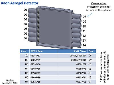
PMTs position in the detector
As in March 13 2013, the following figure shows the PMT position in the Kaon Aerogel Detector. Since the PMT is attached to the shielding, it is not possible to read their serial number anymore. Then the reference for the PMT must be taken using the case number printed on the inner surface of the cylinders.
PMTs at CUA
The group is performing different experiments with some PMT to construct a tool to analyse the equipment that will be used in the aerogel detector.
Since the Summer 2011, the Nuclear Physics group at CUA is performing tests on the following PMTs:
- PMT model XP4500B S/N 09641 (with electronic base #101)
- PMT model XP4500B S/N 09650 (with electronic base #102)
- PMT model XP4500B S/N 01414 (with electronic base #100)
- PMT model XP4500B S/N 09561 (with electronic base #102)
Previous analysis of PMT's gain
The University of South Carolina had analyzed the PMT before it comes to JLab. It was done in the summer of 2011. The plots with the main characteristics of each PMT, separated by its serial number, is shown in Gain Plots.
A table with these data can also be download as a spreadsheet: spreadsheet.
Position dependence of incident photon
Details on the step motor that are being used in the position dependence experiment can be found in the following links:
- Specification
- Drawing BiSlide 50
- Commands to program the hardware: File:StepMotorCommands.pdf
