Difference between revisions of "MainPage:Nuclear:KaonDetector:AerogelCharacteristics"
Jump to navigation
Jump to search
| Line 26: | Line 26: | ||
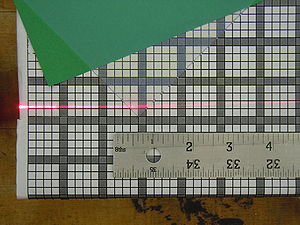
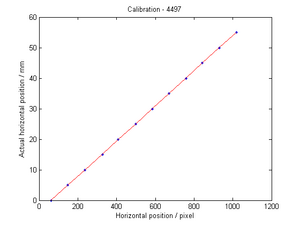
[[File:refracIndex_4497_calib2.png|thumb|center|300px|5) Knowing the grid size of the previous image, the relation pixel to millimeter can be calibrated along the desired line.]] | [[File:refracIndex_4497_calib2.png|thumb|center|300px|5) Knowing the grid size of the previous image, the relation pixel to millimeter can be calibrated along the desired line.]] | ||
| valign="top"| | | valign="top"| | ||
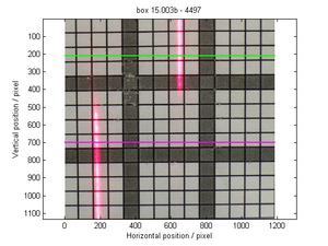
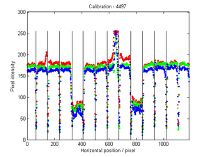
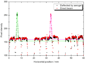
| − | [[File: | + | [[File:refracIndex_4497.png|thumb|center|300px|6) After the calibration of the two lines (directed and refracted beams), the peaks position can be fitted for the analysis of the refracted beam deflection due to the aerogel.]] |
|} | |} | ||
Revision as of 00:33, 11 December 2012
| This page is under construction. |
| ⇐ Back to the Kaon Detector page |
Refractive index measurement
Kaon Aerogel Detector prototype - Aerogel light yield comparison
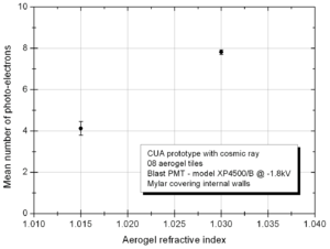
In order to compare the different aerogel (refractive index) we will use in the Kaon Aerogel Detector, a set of cosmic rays data was acquired with the CUA's prototype. Details of the prototype can be found in the Prototype page.
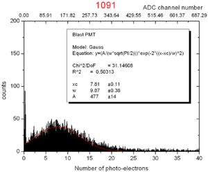
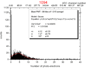
To evaluate the relative light yield of the aerogel tiles with refractive indexes 1.030 and 1.015, the setup was run with the same configuration twice (just exchanging the aerogel).
The setup configuration was kept as follows:
- Cosmic ray configuration (two triggering PMTs with scintillator on the top and bottom of the prototype)
- 08 aerogel tiles
- Mylar covering the internal walls of the prototype
- High voltage of -1.80 kV on the PMT
- Blast PMT for all runs (model XP4500/B s/n 09650, with calibration from run 481)
To see a similar test done for the analysis of the different PMTs options for the Kaon Aerogel Detector, click here.
